
tinkercad-circuits-mcp
# tinkercad-circuits-mcp
An MCP server that builds Arduino circuits in [Tinkercad Circuits](https://www.tinkercad.com/circuits) and runs them in the simulator. You describe the circuit (which part goes in which breadboard hole, the wires, the sketch) and it appears in your Tinkercad account, wired on a breadboard, with the code saved. It can then start the simulation, press buttons, type into the Serial Monitor and tell you what the LEDs, servos and serial output did.
It works with Claude Code, Claude Desktop, Cursor, Codex and any other client that speaks the [Model Context Protocol](https://modelcontextprotocol.io).
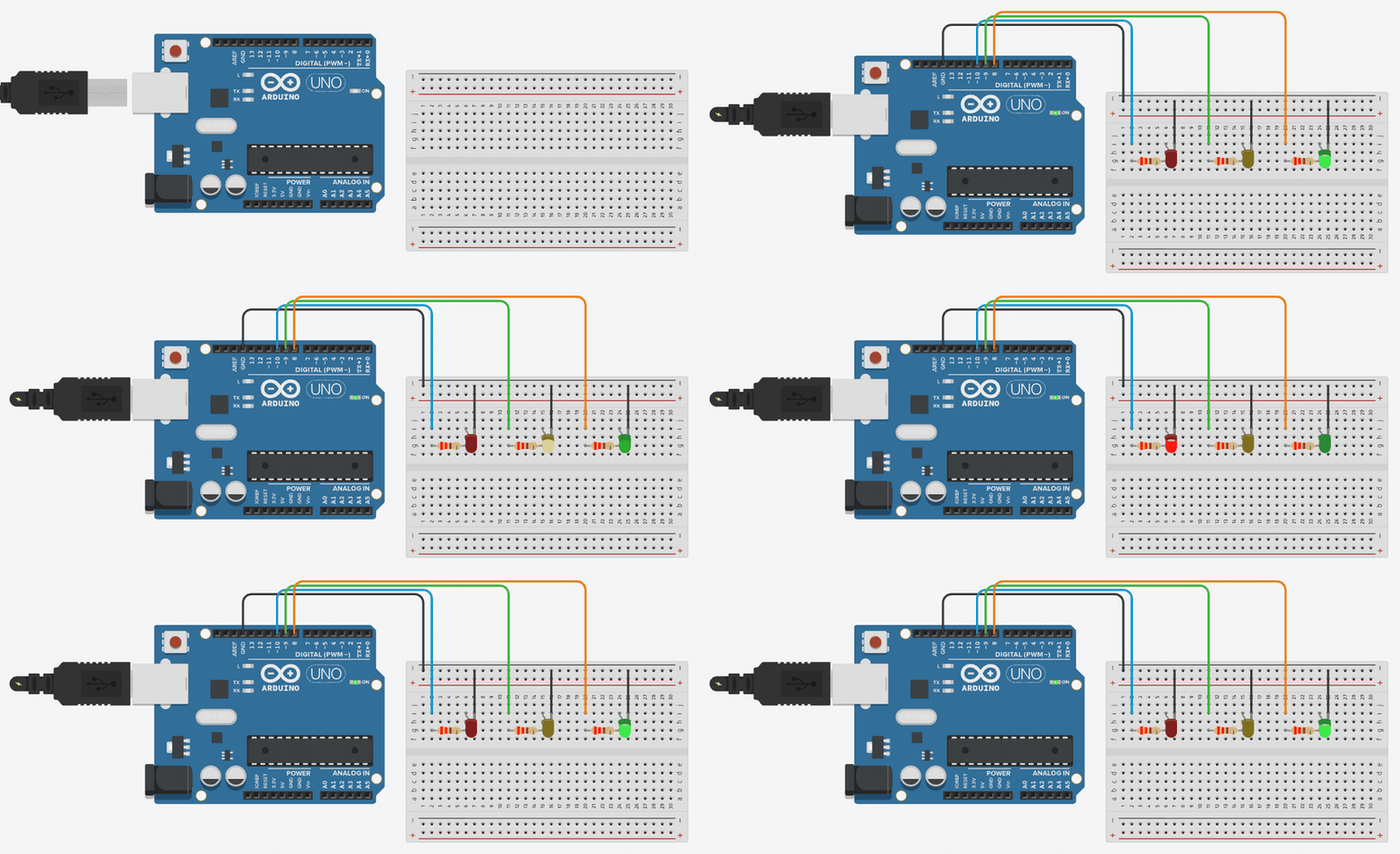
*`examples/traffic-light.json`, built and simulated by the server. The LEDs are read back from the simulator to check the order.*
I wrote it to get through a course with 70-odd Arduino lab tasks that all had to be handed in as Tinkercad designs. Building them by hand took forever.
If you found [sethski/tinkercad-mcp-server](https://github.com/sethski/tinkercad-mcp-server) first: that one works by clicking and dragging in the editor. When I tried it in November 2026 it could not create a circuit or find the breadboard in the parts panel, and it had no way of knowing which hole a leg ended up in. This server changes the editor's circuit model directly, so parts land in the holes you name, and it reads the result back and checks it in the simulator.
> Not affiliated with Autodesk. Tinkercad has no public API for Circuits; this uses the editor's internals, which can change without notice. See [How it works](docs/how-it-works.md).
## What it can do
- Create or open a design and build a whole circuit in one call: Arduino Uno, small breadboard, parts in the holes you name, colour-coded jumper wires routed around the board.
- Write the Arduino sketch into the design.
- Read a design back: every part, the hole under each pin, its settings, every wire, the code.
- Run the simulator and sample LED brightness, servo angles and the Serial Monitor at the times you choose, while pressing buttons or sending serial input.
- Change a setting between runs, like a potentiometer position or the distance an ultrasonic sensor sees, to test different inputs.
About 20 parts are supported: LEDs, resistors, buttons, potentiometers, servos, a piezo, the HC-SR04, TMP36, DC motors (with and without encoder), the L293D, an IR receiver, an RGB LED and a few more. The full list is in [docs/parts.md](docs/parts.md).
## Setup
You need Node.js 20 or newer and Google Chrome. First sign in to Tinkercad once:
```bash
npx -y tinkercad-circuits-mcp login
```
This opens Chrome on the Tinkercad page. Sign in the way you normally do; it is an ordinary Chrome window. It closes once you reach your dashboard. The session lives in `~/.tinkercad-circuits-mcp/profile`; your password never passes through this project.
Then add the server to your client.
### Claude Code
```bash
claude mcp add tinkercad-circuits -- npx -y tinkercad-circuits-mcp
```
### Claude Desktop, Cursor and other clients
Add this to the client's MCP config: `claude_desktop_config.json` for Claude Desktop, `~/.cursor/mcp.json` for Cursor.
```json
{
"mcpServers": {
"tinkercad-circuits": {
"command": "npx",
"args": ["-y", "tinkercad-circuits-mcp"]
}
}
}
```
### Codex
In `~/.codex/config.toml`:
```toml
[mcp_servers.tinkercad-circuits]
command = "npx"
args = ["-y", "tinkercad-circuits-mcp"]
```
### From source
```bash
git clone https://github.com/netchuu/tinkercad-circuits-mcp.git
cd tinkercad-circuits-mcp
npm install
npm run build
npm run login
```
and use `node /full/path/to/tinkercad-circuits-mcp/dist/index.js` as the command in the configs above.
### Skill
There is also a Claude Code skill in [skills/tinkercad-circuits](skills/tinkercad-circuits/SKILL.md) that explains the workflow to Claude: how to lay out a breadboard, what to use when Tinkercad lacks a part, and how to check that a circuit does what the task asks. Copy the folder to `~/.claude/skills/` to use it.
## Using it
Ask for a circuit in plain words:
> Build a traffic light in Tinkercad: red, yellow and green LEDs on pins 10, 9 and 8, green for 5 s, yellow 2 s, red 5 s. Then run it and check the order.
Claude turns that into a spec for `tinkercad_build_circuit`. A smaller one, a single blinking LED, looks like this:
```json
{
"title": "Blink an LED on a breadboard",
"parts": [
{ "ref": "r1", "type": "resistor", "at": "5g", "pin": "1", "angle": 90, "props": { "ohms": 220 } },
{ "ref": "led1", "type": "led", "at": "9i", "pin": "anode", "angle": 180 }
],
"wires": [["uno.GND1", "T-1"], ["uno.D13", "5i"], ["10h", "T-10"]],
"code": "void setup() { pinMode(13, OUTPUT); }\nvoid loop() { digitalWrite(13, HIGH); delay(1000); digitalWrite(13, LOW); delay(1000); }"
}
```
The resistor spans columns 5 to 9 in row g, the LED's anode shares column 9 and its cathode goes to the ground rail. The format is explained in [docs/circuit-spec.md](docs/circuit-spec.md), and there are more complete circuits in [examples/](examples).
To check the circuit, Claude calls `tinkercad_simulate`:
```json
{ "samples_ms": [500, 1500, 2500], "leds": ["led1"] }
```
and gets back, for each sample, whether `led1` was on and the simulator clock at that moment.
## Tools
| Tool | What it does |
| --- | --- |
| `tinkercad_status` | Checks that the Chrome profile is signed in to Tinkercad. |
| `tinkercad_list_parts` | Parts, pin names and settings. |
| `tinkercad_open_circuit` | Opens a design by link or id, or creates a new one. |
| `tinkercad_build_circuit` | Replaces the open circuit with the one in the spec and saves the code. |
| `tinkercad_get_circuit` | Reads the saved circuit back. |
| `tinkercad_set_code` | Replaces the sketch. |
| `tinkercad_set_part` | Changes a part setting (knob position, sensor distance). |
| `tinkercad_simulate` | Runs the simulator with button presses and serial input; returns LED, servo and serial readings. |
| `tinkercad_screenshot` | Returns a picture of the editor. |
## Limits
- One small breadboard per circuit, Arduino Uno only.
- Tinkercad has no KY-023 joystick, LM35, HC-05 Bluetooth module, L298N or IR line sensor. The skill lists the usual stand-ins (two potentiometers, TMP36, the Serial Monitor, L293D, pushbuttons).
- The simulator runs slower than real time, and LED readings come from a screenshot, so leave some margin in your timings. Hold buttons for at least 0.6 s.
- Only one process can use the Chrome profile at a time.
- If Tinkercad changes its editor internals, building will fail until the code is updated. `npm run smoke` tells you quickly whether it still works.
## Documentation
- [Circuit spec](docs/circuit-spec.md): holes, rails, parts, wires, settings
- [Simulation](docs/simulation.md): timelines, reading LEDs, servos and serial, testing a task
- [How it works](docs/how-it-works.md): the Tinkercad internals this relies on
- [Parts](docs/parts.md): every supported part with its pins
- [Troubleshooting](docs/troubleshooting.md)
## Development
```bash
npm test # unit tests for the spec and catalog, no browser needed
npm run smoke # builds and simulates two circuits in your Tinkercad account
npm run parts-doc # regenerates docs/parts.md
```
The smoke test creates a design called "tinkercad-circuits-mcp smoke test". Pass its link to reuse it: `npm run smoke -- https://www.tinkercad.com/things/<id>`.
Issues and pull requests are welcome, especially new parts. Adding one is mostly finding its device id (the `data-did` attribute on the tile in Tinkercad's parts panel) and its pin names; [How it works](docs/how-it-works.md#adding-a-part) has the details.
## License
MIT
TDQS
Scored across 9 tools
Each tool maps to a distinguishable action: status check, part catalog, open/create, build, read state, set code, set a part property, simulate, screenshot. The only soft overlaps are open_circuit vs build_circuit (both can create a circuit) and set_code vs build_circuit's optional code argument, but the descriptions make the primary purpose of each clear enough.
All tools share the tinkercad_ prefix and snake_case, with a mostly verb_noun shape (list_parts, open_circuit, build_circuit, get_circuit, set_code, set_part). tinkercad_status and tinkercad_screenshot are noun-only outliers, but the pattern remains predictable.
Nine tools is well within the sweet spot and every tool covers a distinct phase of the workflow: auth check, discovery, circuit setup, mutation, inspection, simulation, and visual capture. No tool looks redundant or padded.
The surface covers the full loop of discover parts, open/build, read back, tweak code and part settings, simulate, and screenshot, so an agent can accomplish the core task. Gaps are incremental edits (removing a single wire or part, moving a part without a full rebuild) and persistence/export, which are workable via build_circuit replacement but add friction.